Reading multiple analog signals with 1 ADC using the STM32F4 Discovery
Introduction
The STM32F4 has 3 ADCs built in. There are 16 multiplexed channels used to connect the ADCs to the processor. 8 of these are connected to ADC3, while all 16 of the channels are connected to ADC2 and ADC1. Each ADC can convert with a maximum precision of 12bits, meaning that the output of the ADC will range from 0 to 212-1 or, 0 to 4095. The rest of the article looks at how you can use 1 of these ADC’s to read analog signals from 2 or more channels.
Program Overview
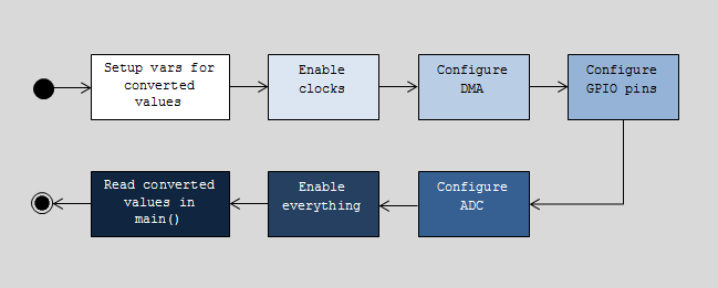
The following flow chart describes the example program we will be looking at.

The Code
1
2
3
4
5
6
7
8
9
10
11
12
13
14
15
16
17
18
19
20
21
22
23
24
25
26
27
28
29
30
31
32
33
34
35
36
37
38
39
40
41
42
43
44
45
46
47
48
49
50
51
52
53
54
55
56
57
58
59
60
61
62
63
64
65
66
67
68
69
70
uint16_t ADC3ConvertedValue[5] = {0,0,0,0,0};
int main(void)
{
    ADC_InitTypeDef       ADC_InitStruct;
    ADC_CommonInitTypeDef ADC_CommonInitStruct;
    DMA_InitTypeDef       DMA_InitStruct;
    GPIO_InitTypeDef      GPIO_InitStruct;
    /* Enable ADC3, DMA2 and GPIO clocks ****************************************/
    RCC_AHB1PeriphClockCmd(RCC_AHB1Periph_DMA2 | RCC_AHB1Periph_GPIOC | RCC_AHB1Periph_GPIOA, ENABLE);
    RCC_APB2PeriphClockCmd(RCC_APB2Periph_ADC3, ENABLE);//ADC3 is connected to the APB2 peripheral bus

    /* DMA2 Stream0 channel0 configuration **************************************/
    DMA_InitStruct.DMA_Channel = DMA_Channel_2;
    DMA_InitStruct.DMA_PeripheralBaseAddr = (uint32_t)&ADC3->DR;//ADC3's data register

    DMA_InitStruct.DMA_Memory0BaseAddr = (uint32_t)&ADC3ConvertedValue;
    DMA_InitStruct.DMA_DIR = DMA_DIR_PeripheralToMemory;
    DMA_InitStruct.DMA_BufferSize = 5;
    DMA_InitStruct.DMA_PeripheralInc = DMA_PeripheralInc_Disable;
    DMA_InitStruct.DMA_MemoryInc = DMA_MemoryInc_Enable;
    DMA_InitStruct.DMA_PeripheralDataSize = DMA_PeripheralDataSize_HalfWord;//Reads 16 bit values

    DMA_InitStruct.DMA_MemoryDataSize = DMA_MemoryDataSize_HalfWord;//Stores 16 bit values

    DMA_InitStruct.DMA_Mode = DMA_Mode_Circular;
    DMA_InitStruct.DMA_Priority = DMA_Priority_High;
    DMA_InitStruct.DMA_FIFOMode = DMA_FIFOMode_Disable;
    DMA_InitStruct.DMA_FIFOThreshold = DMA_FIFOThreshold_HalfFull;
    DMA_InitStruct.DMA_MemoryBurst = DMA_MemoryBurst_Single;
    DMA_InitStruct.DMA_PeripheralBurst = DMA_PeripheralBurst_Single;
    DMA_Init(DMA2_Stream0, &DMA_InitStruct);
    DMA_Cmd(DMA2_Stream0, ENABLE);
    /* Configure GPIO pins ******************************************************/
    GPIO_InitStruct.GPIO_Pin = GPIO_Pin_0 | GPIO_Pin_1 | GPIO_Pin_2 | GPIO_Pin_3;// PC0, PC1, PC2, PC3

    GPIO_InitStruct.GPIO_Mode = GPIO_Mode_AN;//The pins are configured in analog mode

    GPIO_InitStruct.GPIO_PuPd = GPIO_PuPd_NOPULL ;//We don't need any pull up or pull down

    GPIO_Init(GPIOC, &GPIO_InitStruct);//Initialize GPIOC pins with the configuration

    GPIO_InitStruct.GPIO_Pin = GPIO_Pin_1;//PA1

    GPIO_Init(GPIOA, &GPIO_InitStruct);//Initialize GPIOA pins with the configuration

    /* ADC Common Init **********************************************************/
    ADC_CommonInitStruct.ADC_Mode = ADC_Mode_Independent;
    ADC_CommonInitStruct.ADC_Prescaler = ADC_Prescaler_Div2;
    ADC_CommonInitStruct.ADC_DMAAccessMode = ADC_DMAAccessMode_Disabled;
    ADC_CommonInitStruct.ADC_TwoSamplingDelay = ADC_TwoSamplingDelay_5Cycles;
    ADC_CommonInit(&ADC_CommonInitStruct);
    /* ADC3 Init ****************************************************************/
    ADC_DeInit();
    ADC_InitStruct.ADC_Resolution = ADC_Resolution_12b;//Input voltage is converted into a 12bit int (max 4095)

    ADC_InitStruct.ADC_ScanConvMode = ENABLE;//The scan is configured in multiple channels

    ADC_InitStruct.ADC_ContinuousConvMode = ENABLE;//Continuous conversion: input signal is sampled more than once

    ADC_InitStruct.ADC_ExternalTrigConv = 0;
    ADC_InitStruct.ADC_ExternalTrigConvEdge = ADC_ExternalTrigConvEdge_None;
    ADC_InitStruct.ADC_DataAlign = ADC_DataAlign_Right;//Data converted will be shifted to right

    ADC_InitStruct.ADC_NbrOfConversion = 5;
    ADC_Init(ADC3, &ADC_InitStruct);//Initialize ADC with the configuration

    /* Select the channels to be read from **************************************/
    ADC_RegularChannelConfig(ADC3, ADC_Channel_10, 1, ADC_SampleTime_144Cycles);//PC0

    ADC_RegularChannelConfig(ADC3, ADC_Channel_11, 2, ADC_SampleTime_144Cycles);//PC1

    ADC_RegularChannelConfig(ADC3, ADC_Channel_12, 3, ADC_SampleTime_144Cycles);//PC2

    ADC_RegularChannelConfig(ADC3, ADC_Channel_13, 4, ADC_SampleTime_144Cycles);//PC3

    ADC_RegularChannelConfig(ADC3, ADC_Channel_1,  5, ADC_SampleTime_144Cycles);//PA1

    /* Enable DMA request after last transfer (Single-ADC mode) */
    ADC_DMARequestAfterLastTransferCmd(ADC3, ENABLE);
    /* Enable ADC3 DMA */
    ADC_DMACmd(ADC3, ENABLE);
    /* Enable ADC3 */
    ADC_Cmd(ADC3, ENABLE);
    /* Start ADC3 Software Conversion */
    ADC_SoftwareStartConv(ADC3);
    while(1)
    {
    }
    return 1;
}
The above code reads in analog voltages from 5 pins, namely PC0, PC1, PC2, PC3 and PA1. ADC3 is then used to convert each analog voltage into a 16 bit integer (with only 12 bit precision - the most significant 4 bits are 0). The ADC samples every 144 clocks cycles, and the DMA transfers these integers to memory (referenced by the array defined on line 1).
Tailoring for your project
Changing the GPIO pins
To modify the GPIO pins used, just change lines 34-39 with your required pins. You will also need to configure the channels at lines 60-64. The following table was derived from the STM32F4 Discovery user manual (UM1472) and can be used to determine which pins are connected to which ADC and via which channel.
| Pin | Channel | |
|---|---|---|
| ADC1/2/3 | PA0 | 0 |
| PA1 | 1 | |
| PA2 | 2 | |
| PA3 | 3 | |
| PC0 | 10 | |
| PC1 | 11 | |
| PC2 | 12 | |
| PC3 | 13 | |
| ADC1/2 | PA4 | 4 |
| PA5 | 5 | |
| PA6 | 6 | |
| PA7 | 7 | |
| PB0 | 8 | |
| PB1 | 9 | |
| PC4 | 14 | |
| PC5 | 15 |
Note: PA0 is also used for the User Button (the blue button).
Increasing/decreasing the number of pins
First, the array on line 1 should be adjusted to your desired size.
uint16_t ADC3ConvertedValue[5] = {0,0,0,0,0};You will then need to change the DMA buffer size on line 19.
DMA_InitStruct.DMA_BufferSize = 5;Finally, you will have to also change the number of ADC conversions on line 56.
ADC_InitStruct.ADC_NbrOfConversion = 5;Don’t forget to configure the GPIO pins in lines 34-39, as well as the channels in lines 60-64.
Source code
You can download the source code for this simple program here: source
